MST
RFQ cartCart

Can't find it? We'll source it — and check it fits.

An MST engineer will review your requirement and reply to help with sourcing and compatibility.

Request sourcing & fit check

Breakout and evaluation boards

5 products

Showing 1–5 of 5

5 products · final price and lead time on quote

Compare specifications

Review model numbers, published specifications and reference documents together. Open a product for its complete data and current purchasing terms.

Showing 5 of 5 products

Values are reproduced from the published product data. A listed application is a selection reference; check the exact configuration for your equipment.
Model / material gradePublished application or usePublished specificationsPurchase or quote
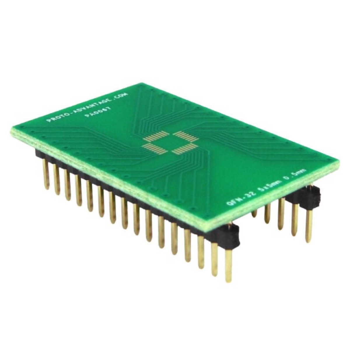
PA0067BRK-QFN32-DIPProto-Advantage PA0067 QFN-32 (0.5 mm, 5 × 5 mm) to DIP-32 SMT adapterSee product details
Selection and part-number notes
  • Footprint match: PA0067 adapts QFN32, 5 × 5 mm, 0.5 mm pitch, to DIP32 / 600 mil. This is an SMT breakout board; the IC must be assembled to its pads.
  • Assembly check: Compare the complete land pattern, pin numbering and exposed-pad routing with your IC drawing. Confirm header assembly, soldering method and required stencil before choosing accessories.
Package
QFN-32
Pin count
32
Dimensions
Body 5 × 5 mm
Specification
0.5 mm pitch → DIP-32 (600 mil)
Material
FR4 1.6 mm, ENIG
View product and request a quote
Product sources
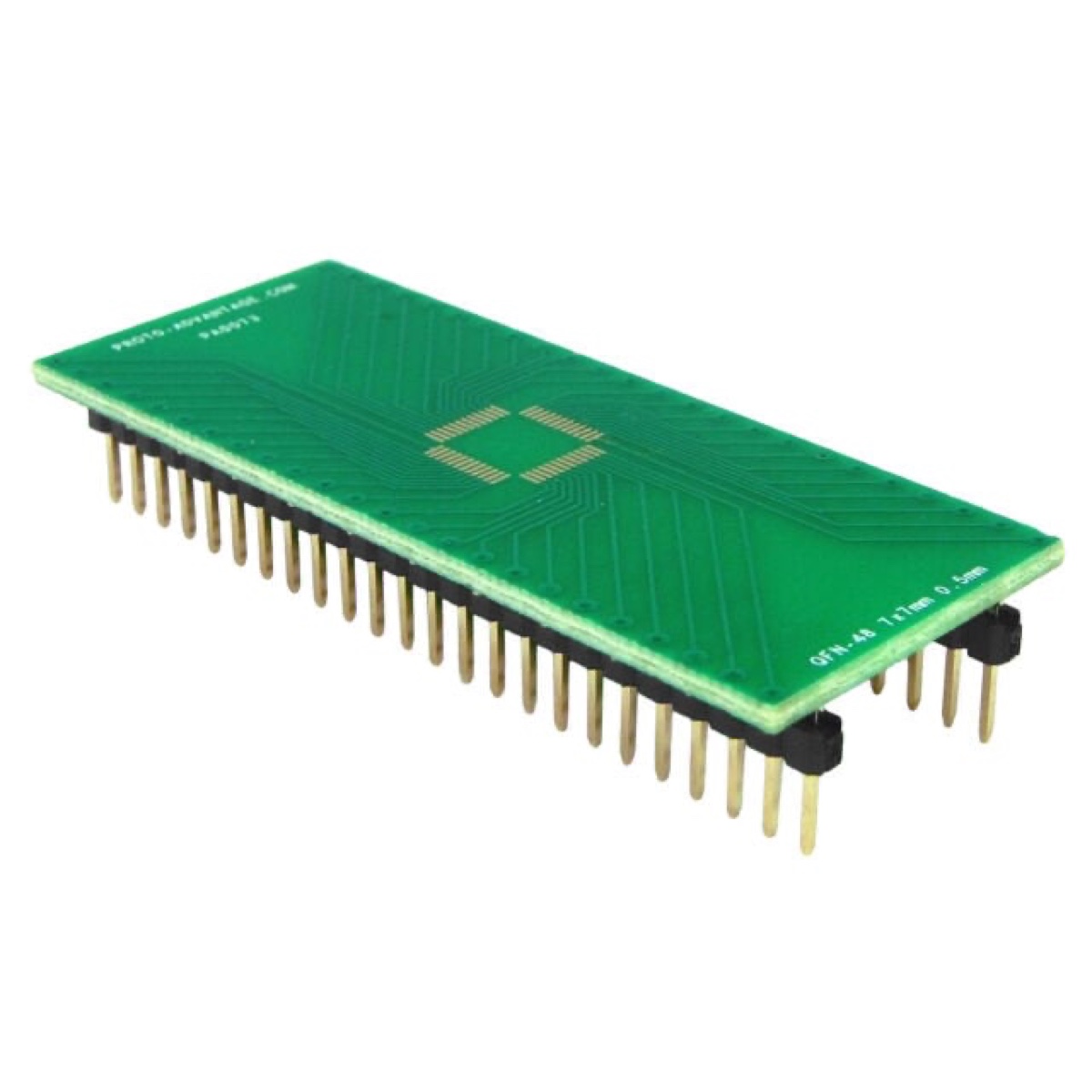
PA0073BRK-QFN48-DIPProto-Advantage PA0073 QFN-48 (0.5 mm, 7 × 7 mm) to DIP-48 SMT adapterSee product details
Selection and part-number notes
  • Adapter or test socket: This is a QFN48-to-DIP48 breakout adapter for board-level prototyping. It is not a clamshell test socket and does not provide an empty cavity for die attach or wire bonding.
  • Which QFN48 footprint: The referenced PA0073 format is 7 x 7 mm with 0.5 mm pitch and a 600 mil DIP row spacing. A 6 x 6 mm, 0.4 mm-pitch QFN48 device is a different footprint.
  • Assembly and connection: Review the pad map, pin-1 orientation, exposed-pad treatment, soldering process and required headers before ordering. Do not assume sockets, headers or chip assembly are included.
  • Before requesting a quote: Send the exact IC part number and package drawing, quantity, target board connection and any assembly needs. Confirm included items and lead time in the quotation.
Package
QFN-48
Pin count
48
Dimensions
Body 7 × 7 mm
Specification
0.5 mm pitch → DIP-48 (600 mil)
Material
FR4 1.6 mm, ENIG
View product and request a quote
Product sources
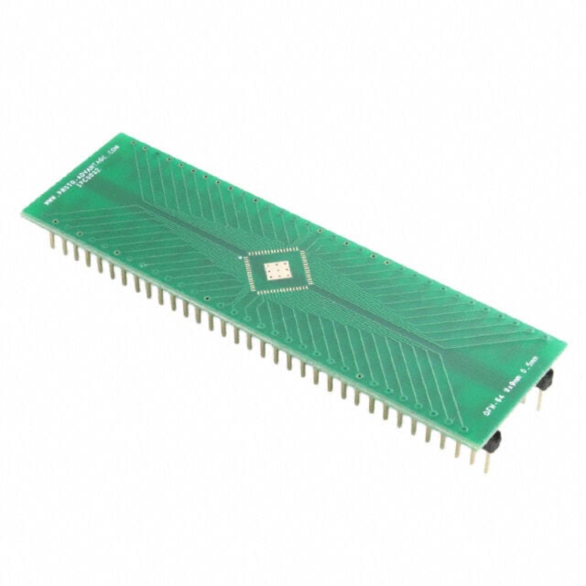
IPC0032BRK-QFN64-DIPProto-Advantage IPC0032 QFN-64 (0.5 mm, 9 × 9 mm, 3.8 mm pad) to DIP-68 SMT adapterSee product details
Selection and part-number notes
  • Footprint match: IPC0032 adapts QFN64, 9 × 9 mm, 0.5 mm pitch, to DIP68 / 600 mil. This is an SMT breakout board; the IC must be assembled to its pads.
  • Assembly check: Compare the complete land pattern, pin numbering and exposed-pad routing with your IC drawing. Confirm header assembly, soldering method and required stencil before choosing accessories.
  • Exposed pad: IPC0032 uses 68 DIP positions for 64 signal connections plus four pad connections. Check the 3.8 × 3.8 mm central pad and its mapping; it is not a 64-position DIP footprint.
Package
QFN-64
Pin count
64
Dimensions
Body 9 × 9 mm
Specification
0.5 mm pitch → DIP-68 (600 mil; 64 signal + 4 pad pins)
Material
FR4 1.6 mm, ENIG
View product and request a quote
Product sources
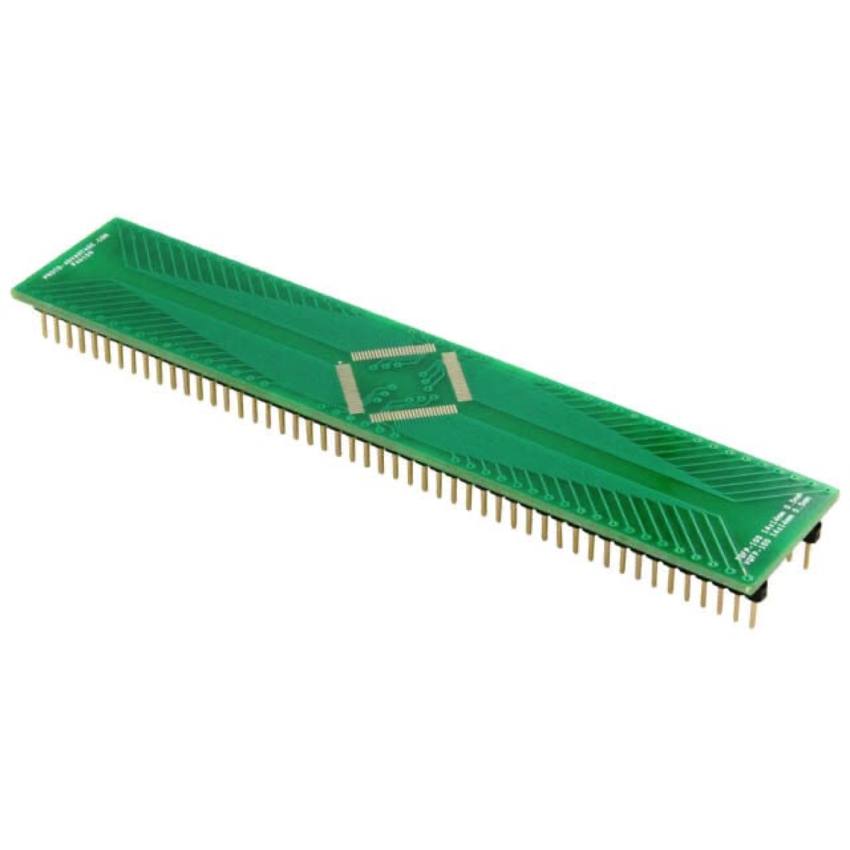
PA0109BRK-QFP100-DIPProto-Advantage PA0109 TQFP/VQFP-100 (0.5 mm, 14 × 14 mm) to DIP-100 SMT adapterSee product details
Selection and part-number notes
  • Footprint match: PA0109 adapts TQFP/VQFP/LQFP100, 14 × 14 mm, 0.5 mm pitch, to DIP100 / 600 mil. This is an SMT breakout board; the IC must be assembled to its pads.
  • Assembly check: Compare the complete land pattern, pin numbering and exposed-pad routing with your IC drawing. Confirm header assembly, soldering method and required stencil before choosing accessories.
Package
TQFP-100 / VQFP-100 / LQFP-100
Pin count
100
Dimensions
Body 14 × 14 mm
Specification
0.5 mm pitch → DIP-100 (600 mil)
Material
FR4 1.6 mm, ENIG
View product and request a quote
Product sources
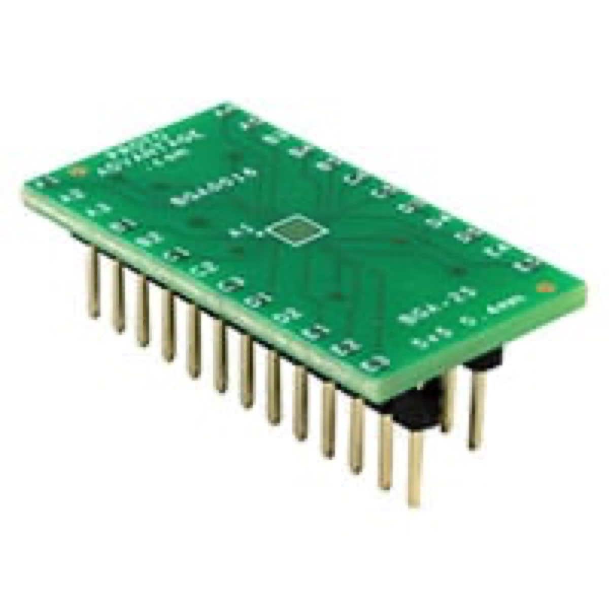
BGA0016BRK-WLCSP-EVALProto-Advantage BGA0016 BGA/WLCSP-25 (0.4 mm, 5 × 5 grid) to DIP-25 SMT adapterSee product details
Selection and part-number notes
  • Footprint match: BGA0016 adapts BGA25, 5 × 5 ball grid, 0.4 mm pitch, to DIP25 / 300 mil. This is an SMT breakout board; the IC must be assembled to its pads.
  • Assembly check: Compare the complete land pattern, pin numbering and exposed-pad routing with your IC drawing. Confirm header assembly, soldering method and required stencil before choosing accessories.
  • Grid versus body: 5 × 5 describes the ball array, not a 5 × 5 mm body. Match ball diameter, pad map and the actual package outline to the BGA0016 drawing before assuming WLCSP compatibility.
Package
BGA-25 / WLCSP-25
Pin count
25
Dimensions
5 × 5 ball grid; package body dimensions require drawing confirmation
Specification
0.4 mm pitch → DIP-25 (300 mil)
Material
FR4 1.6 mm, ENIG
View product and request a quote
Product sources

Looking for a replacement? Send the model number and request a quote.

Technical guides and sources

Need help confirming the specification?

Send the known manufacturer or part number, drawing or dimensions, quantity, destination and required date. Include the equipment and operating conditions when suitability needs to be checked.

Start with the information you have. We can help clarify missing details before quoting.

Ask MST about this requirement